REBUILDING THE SUPERBIRD FRONT SUSPENSION
Photos by Sue George; Text by Sue and Ed George and Benton Warnke
You probably won't notice that the front end of your old Mopar is getting saggy and worn out. Those factory rubber bushings and steering parts, like tie rods and ball joints, weren't meant to last a lifetime and most of these cars are pushing 35-40 years now. These parts wear out so gradually you won't realize how bad everything is until until your car's geometry is so far off that a front end alignment won't hold, your front tires wear out prematurely and you will start to hear lots of squeaking and noise, assuming you drive the car. Replacing all of these parts is not a job for the faint of heart. Your car will end up on blocks with literally nothing under the front! And it does take a couple of special tools and about $500 worth of new parts. But the end result is like driving a brand new car.
To begin, I'd like to thank our good friend and fellow club member, Benton Warnke from Carroll, IA for recommending what parts I should order and for spending an entire day here helping us rebuild the front end of my Superbird. Ben told us that he learned to perform the front end rebuild out of necessity back in the early 90's when he shopped around to hire the job done on his old Duster and found that it cost over $800 to do one side of the car. Imagine what this would cost today! It was great to have someone helping who knew what they were doing, so a big Thank You to Ben for all the help with my car and this tech article.
We used the PST brand #FEKS Polygraphite Super Kit, which includes the sway bar bushing kit. Polygraphite bushing are supposed to be superior to the factory rubber bushings. The only variable you will need to know about when ordering the kit is your front sway bar diameter so they can send you the correct hardware. Call PST at (972) 299-8019.
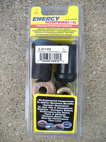
Also, the PST kit comes with rubber lower control arm bushings. They claim they cannot get these in the polygraphite material, however we ordered these in polygraphite made by Energy Suspension (Part #5-3112G) from Mancini Racing in Michigan, phone 1-800-843-2821.
With the car on a level surface, you need to measure the distance between the ground and a point somewhere on the front end (such as the front of the rocker panel or the fender) and write this measurement down. You can use this measurement for a reference to return the car to close to its previous height by screwing the torsion bar adjustment bolt in or out.
Begin by blocking the rear wheels, raise the car and put it on blocks at a sufficient height to remove the front wheels. Remove the front tires/wheels. Loosen the torsion bar adjusting bolt (this is the bolt that goes up through the lower control arm from the bottom) to release the pre-load. This is very important because when you start taking all the components apart, there will be tremendous pressure on them from the torsion bars and if you don't release this pressure first, it's like working with a loaded gun.
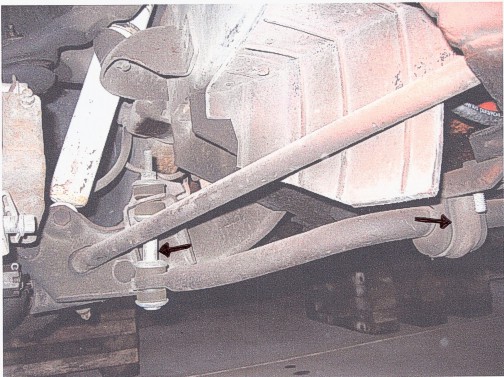
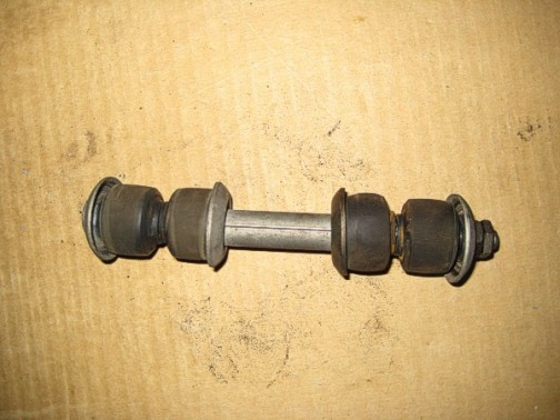
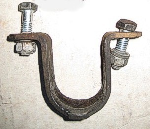
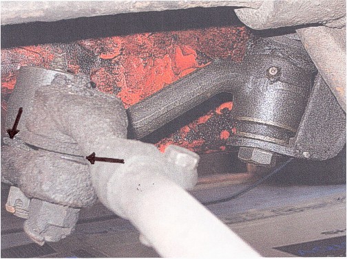
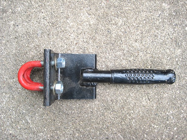
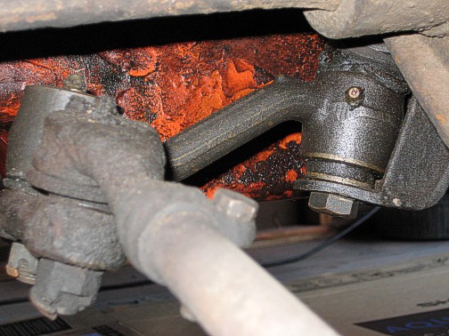
Remove the front sway bar using 1/2" and 9/16" wrenches or sockets. Take the link bolt and the hardware out of the sway bar and the lower control arms on each side of the car. Then remove the retainer brackets from the front cross-member. Turn the sway bar towards the front of the car and slide it out through the opening in the front cross-member. The arrow at the right of the first photo below shows the sway bar retainer bracket and the arrow at the left shows the sway bar link bolt. The second photo shows the link bolt assembly and the third photo shows the sway bar retainer bracket.
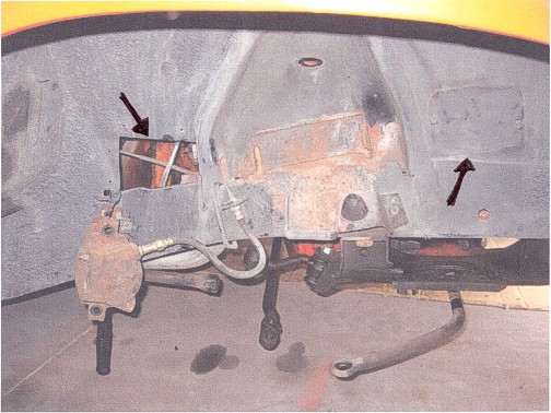
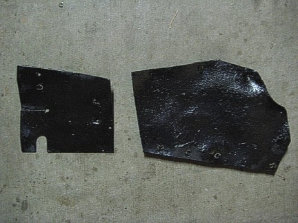
Take off the access opening covers (one at each end of the upper control arm). These are just rubber flaps that are held on with little clips that you can pry off. The front cover on the passenger side of the car has two small bolts holding it on. The rear cover on the passenger side goes in from the engine side of the inner fender. The photos below show the covers on the car (arrows) and off the car. There are two covers on each side.
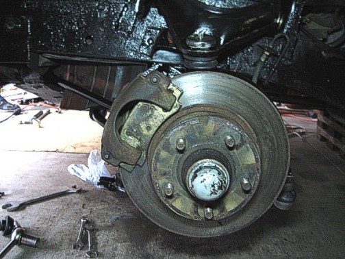
Remove the brake caliper and tie it up out of the way. Remove the shock absorber. Remove the wheel bearing and the rotor.
Next remove the tie rod assembly by removing the cotter key then use a 3/4" socket to remove the nut from both ends of the tie rod. Separate the tie rod end with a pickle fork. Insert the fork between the tie rod end and the knuckle arm behind the brake dust shield. Separate them by hitting the fork with a hammer. Repeat this procedure at the other end of the tie rod between the tie rod end and the center link.
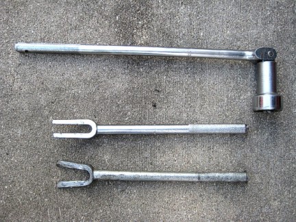
Remove the cotter keys and nuts on the idler arm-to-center link and both tie rods. Use the pickle fork to separate the idler arm and the other tie rod from the center link and lower ball joint. The photos below are from left to right: These are tools you will need, a ball joint socket and pickle forks of various sizes; the arrow points to where you separate the inner tie rod end and the idler arm from the center link; the third photo shows where the separation is to remove the outer tie rod end; the last photo shows the tie rod assembly removed.
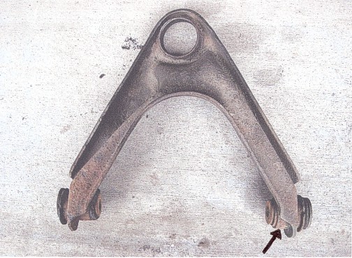
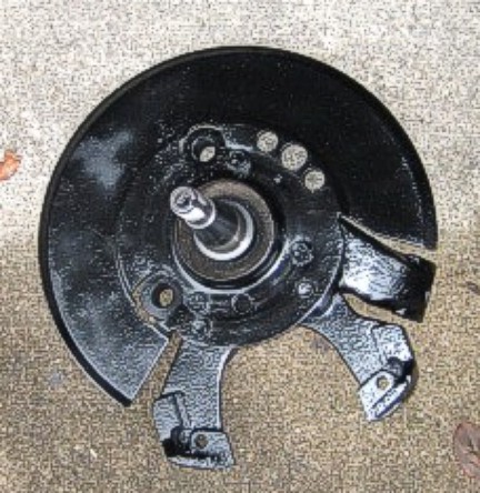
Remove two bolts that hold the lower ball joint to the spindle with a 15/16" socket. Take the cotter key and nut off the lower ball joint knuckle with a 7/8" socket. Take the cotter key and nut off the upper ball joint knuckle with the same socket. Use a small pickle fork to separate the lower ball joint from the lower control arm. Use the larger pickle fork to separate the upper ball joint from the spindle. Remove the lower ball joint and spindle. The photo below shows the back side of the brake dust shield with the lower ball joint still attached to the lower control arm. The arrow points to the bolts that holds the lower ball joint to the brake dust shield and the back of the spindle.

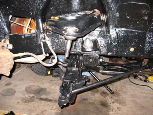
Remove the upper ball joint using a 1-7/8" ball joint socket (Snap-On part #S9365B). The upper ball joints unscrew; they are not pressed in! (Ben has sold many upper control arms because people have damaged them trying to press out the ball joint). This will be extremely tight and you may need to use a pipe for extra leverage. The photo below shows the upper ball joint still in the upper control arm on the car. If you do not have a large vise, you will want to remove the ball joint while the upper control arm is still on the car.
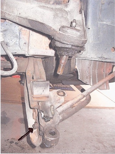
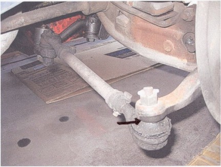
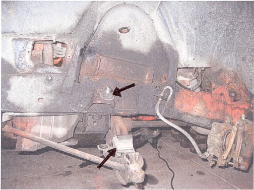
Remove the spring pin (roll pin) and then the strut rod nut on the front of the cross-member. There are two bolts up through the plastic shield on the frame that hides the 15/16" nut that holds the strut rod. The nut on the lower part of the strut rod that goes through the lower control arm is 3/4". Refer to the photo above: the arrow points to the nut that needs to be removed from the strut rod.
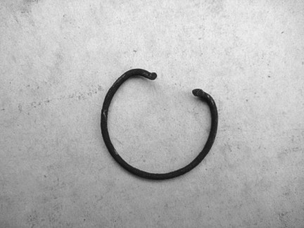
Remove the torsion bar lock ring from the frame. They are located on both sides of the rear side of the transmission cross-member. Grab the top of this wire ring with pliers and pull it down and back toward you. Photos below: The arrow points to the end of the torsion bar in the frame as seen from the rear side of the transmission cross-member. This is officially called the "torsion bar rear anchor". This is what the lock ring looks like after it is removed from the torsion bar end.

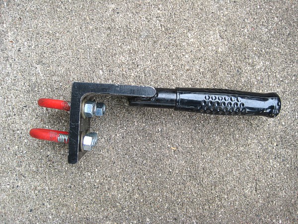
Clamp a torsion bar removal tool on the torsion bar far enough behind the lower control arm so that you can tap on it with a hammer while twisting and shoving the torsion bar toward the rear of the car. Do not apply any heat to any portion of the torsion bar! Iowa member Stan McGuire makes a torsion bar removal tool that works perfectly for this job as shown below. it is $25 plus actual shipping to you. You can call Stan at (515) 223-4763 or email to him at Sm69beep@aol.com.
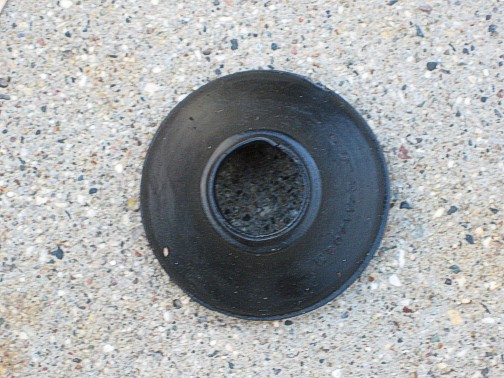
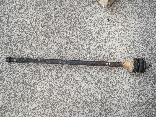
Slide the torsion bar out toward the rear of the car and remove the balloon seal which is on the front of the torsion bar anchor. You will have to order new balloon seals (shown below) from Chrysler as they are not part of the PST kit. The seals are part #2071173 and you will need two of them.
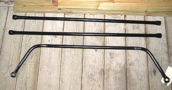
Remove the torsion bar. The bars are marked left and right (L and R) and they must be reinstalled on their correct side. The photo below shows the front sway bar and the torsion bars, cleaned up and I painted mine black, but to be correct they should be bare metal.
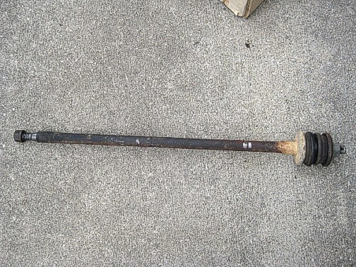
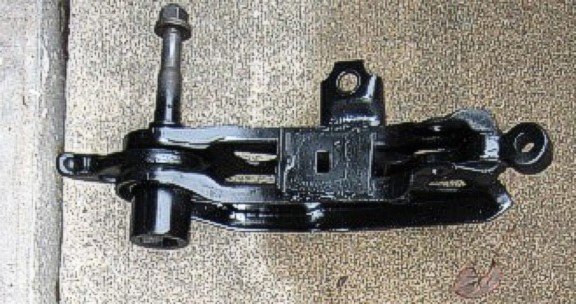
Remove the nut off the front of the lower control arm shaft and slide the lower control arm back out of the K-frame along with the strut rod. The first photo below shows the lower control arm and shaft. Remove all the bushings from the strut rod. Note the order in which the bushings and washers are installed on the original rod as shown below in the photo at right.

Remove the front and rear cam bolts that hold the upper control arm. They are accessed from the holes that you previously removed the rubber covers from. Remove the upper control arm. Clean all of the lower and upper control arm assemblies very well before taking them to the machine shop. "Cleanliness" is the key word when working with the polygraphite parts. Everything needs to be very clean when you get ready to reassemble it. The photo below shows the upper control arm and the cam bolts after removal from car.

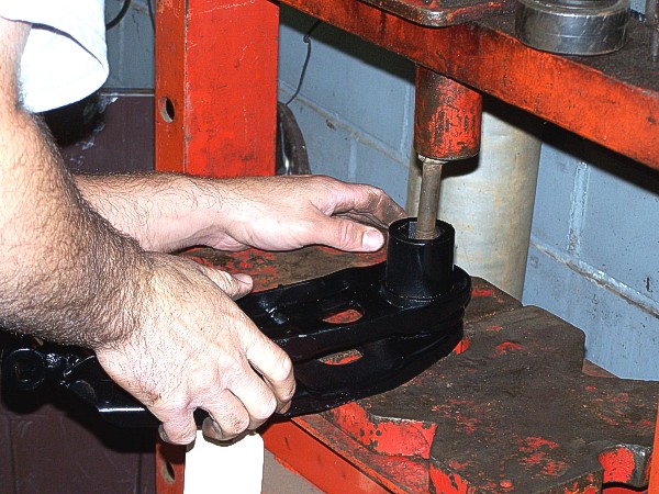
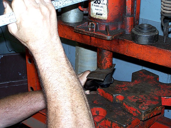
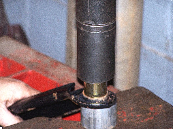
At the machine shop, the shaft needs to be pressed out of the lower control arm. If you use the polygraphite insert, you will need to remove the old rubber insert from the original bushing. If possible, this needs to be removed without damaging the outer metal sleeve. Clean the metal sleeve real well and inspect it for excessive wear and damage. If the sleeve is in good reusable condition, use the lube supplied with the new polygraphite bushings and apply it to the new polygraphite insert. Install the polygraphite insert into the old metal sleeve and then the machinist can press the shaft into the new bushing. If the metal sleeve is damaged or otherwise unusable, you will need to remove it from the control arm and press it into the new bushing assembly supplied in the PST kit. Then you will have to remove the rubber insert (remember, PST does not supply a polygraphite bushing for the lower control arm) without damaging the new metal sleeve and replace the rubber with the polygraphite insert after lubing it. In other words, you are just exchanging the rubber insert in the PST bushing with the polygraphite insert from Mancini. The photos below are as follows: the first two photos show the machinist pressing the shaft out of the lower control arm bushing; the third photo shows the new bushing insert ready to install in the lower control arm. The fourth photo shows the package of Energy Suspension polygraphite lower control arm bushings purchased from Mancini Racing. The components in the last photo are as follows: the two inserts at the top left are Energy Suspension's polygraphite parts. The two metal sleeve/insert assemblies in the center are the rubber ones from PST. The four metal sleeves shown at the bottom left are are Energy Suspension's upper control arm bushings and these will not be used because you will be using the ones from PST which are shown in the bag at the far right in this photo.
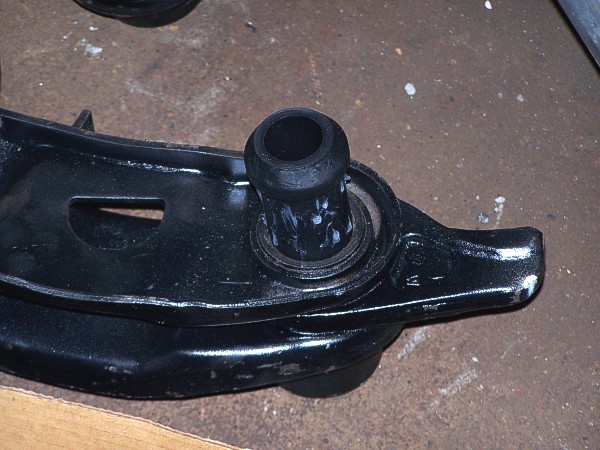

After installing the bushing insert, the machinist will press the shaft back into the lower control arm bushing. The lower control arm is now rebuilt.
Next the machinist needs to press the old bushings out of the upper control arm from the inside-out (shown in first photo below). The machinist needs to be very careful with the bushing support sleeve as it is easily damaged. He will then press the new bushings into the upper control arm with the tapered part of the bushing seats on the arm. The bushing support sleeve will be pressed onto the rear bushing only. Perform the same procedure for the other control arm. You are now finished at the machine shop. Note: The sleeve (arrow in the photo at right below) is used on models with 10" brakes and on police and taxi applications, which includes Superbirds.
You are now ready to reassemble the front end components. **A SPECIAL NOTE FROM BEN: Whenever you install a cotter key, if the holes don't line up, NEVER BACK THE NUT OFF! Always tighten it a little tighter until the holes line up.
Assuming you have cleaned, painted, powder-coated, etc. all the parts that need be, you will begin by finding the new cam bolts in your PST kit (shown below) and the upper control arm. Coat the sides of the cam bolts with anti-seize compound. Place the upper control arm in its position (refer to the second photo below) and install the cam bolts through the body support bracket and through the upper control arm. Roughly center the cam bolts in the slot, apply anti-seize compound to the nuts and tighten them. (The front-end shop will have to loosen these when they align the front end so they don't need to be torqued to specs now).

Find the new upper ball joint seal, nut and washer, grease zerk and cotter pin in your kit (shown below) and screw the ball joint into the hold in the upper control arm and tighten it until it bottoms on the housing. Then tighten to a minimum of 125 foot-pounds. Position a new seal over the ball joint stud. You can use a large (2") socket to push the seal up onto the ball joint housing until it is fully seated. Screw the new grease zerk into the top of the ball joint.

Now you're ready for the lower control arm assembly and the old strut rod and your new bushings and new sleeve in your PST kit (all shown below). Place the strut rod in the hole in the lower control arm and then install the nut. Tighten to 100 foot-pounds. Then install an old washer on the strut rod, a new polygraphite bushing with the cone (tapered) end facing the washer. Then lift the assembly and align the strut rod with the hole in the front cross-member, and the shaft on the lower control with the hole in the rear of the cross-member. Slide the assembly all the way in and install a washer and a nut on the shaft on the lower control arm just finger-tight for now. Place the sleeve on the strut rod, then the bushing with the cone (taper) facing the front of the car, then the washer and nut. Tighten finger-tight for now.

Install your new lower ball joint (shown below) on the lower control arm. The bolt goes through the hole from the bottom and the nut is tightened to 85 foot-pounds and the cotter key is installed (there's a hole through the stud that lines up with one of the slots in the nut).
Install the bumper on the lower control arm. There is a pad on the top center of the lower control arm. The threaded stud goes through the hole and the nut goes to the bottom. We could find no torque rating for these nuts, so just make them tight. Turn the bumper so its ridge is parallel to the car's frame.
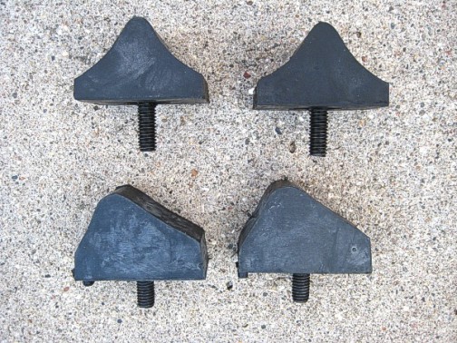
**Before you ever start the rebuild, inspect your new parts to make sure you have everything and it's correct. The PST kit we received had the wrong lower control arm bumpers in it. These are the bottom two shown in the photo below. The correct bumpers that you should use are shown at the top of the photo. With a quick phone call, PST was happy to send the correct ones and even over-nighted them to us! It was a pleasure to deal with this company, as they went out of their way to help us. Not knowing for sure just what we should have in our kit to begin with, the PST technician went through everything we received and told us what it was and how many there should be in the box.
Install the upper control arm bumper next (shown below). This goes on the frame just below the upper control arm. Install them with the threads down, screw the nut on from below and tighten. The second photo below has an arrow showing the location of these two bumpers.

Next, install the brake support and spindle assembly (shown below). Slide the top knuckle on the upper ball joint stud and install the nut finger-tight. At the bottom of the brake dust shield (what some people refer to as the backing plate), there are to large holes for bolts that attach it to the lower ball joint. The bolts are installed with the nuts to the back side of the lower ball joints. In other words, the bolts go in from the outside so you can see the heads from the outside. The torque ratings are as follows: 85 foot-pounds for the lower ball joint nuts and 100 foot-pounds for the upper ball joint nuts. Tighten these next and align the nuts so you can install the cotter keys.
You are ready to install the torsion bars now. Place the new polygraphite boot over the end of the torsion bar with the large end of the boot facing down and slide it 2/3 of the way down the bar. It will be much easier to install the boot if you lube it first (any kind of lube, spray or grease, etc). You will have to keep stretching and pulling at it until it goes over the end of the torsion bar--it is difficult to get it started on. Now put the end of the torsion bar that the large end of the boot is facing into the hole in the frame (the small tapered end of the boot faces the front of the car) and rock it back and forth until it lines up and slides through. Insert the front of the torsion bar into the hex hole in the lower control arm and slide it in until it bottoms. You may need to use Stan's special torsion bar tool and a hammer to tap it until it bottoms. Install the lock ring into the groove in the frame at the rear end of the torsion bar.

Fill the hole in the frame, where the torsion bar passes through, with grease. We used Mopar Multi Mileage Lube part #04897841AA. It is available from your local Chrysler dealer for about $9 a tube. Slide the boot down the torsion bar and snap it onto the cross-member (you can feel it when it clips to the frame).

Install the swivel for the torsion bar adjusting bolt (swivel and bolt shown below) into the slot in the lower control arm and screw in the adjusting bolt until it reaches the place on the bolt where it was originally rusty (this will be close to the original right height).

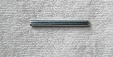
Now you're ready to tighten the lower control arm. Tighten the lower control arm pivot shaft nut to 145 foot-pounds. Next tighten the front strut rod nut to 52 foot-pounds and insert the spring pin (commonly referred to as a roll pin--shown below) that you removed or replace it with a new one from the hardware store or auto parts store. This spring pin does not come in your PST kit.
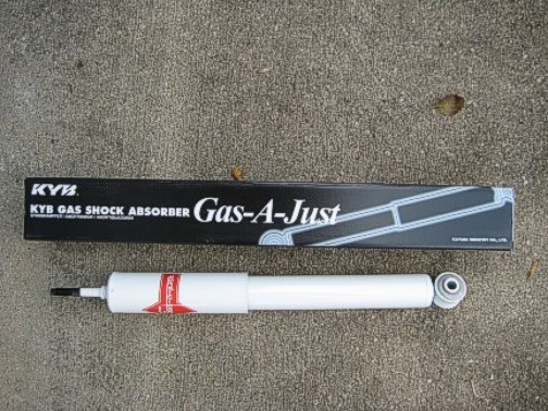
Next install the shock absorber. If you haven't replaced them lately, now is the time to do so. We used KYB Gas-A-Just, purchased at www.RockAuto.com (ask for your club discount when you order them). These are firmer than OEM shocks.
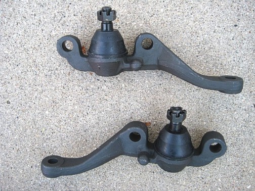
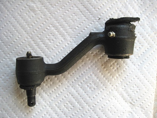
Install the new idler arm from your PST kit. Our old one is shown on the left below. Install the bolt with the nut on the bottom. Tighten the nut to 65 foot-pounds and install the cotter pin. Place the idler arm stud through the center link and tighten the nut to 40 foot-pounds. Install the cotter pin. At right below is the new idler arm installed on the car.
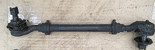
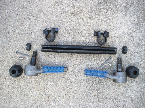
Now you're ready to assembly your new tie rod and ends. The parts in your PST kit are shown below. Remove the plastic thread protectors from the tie rod ends. Lube the threads on each tie rod end with anti-seize compound. Slide the clamps over the tie rod ends, one at each end, making sure the clamp bolts are facing the same direction. Then screw the tie rod end in approximately 4 to 5 turns. (One tie rod end is left-handed threads, the other is right-handed threads. They screw in real easy, so make sure you have the correct one on each end so as not to damage the threads). Now refer to your old tie rod ends for the total length measurement. Holding the tie rod ends, have someone turn the tie rod (in the center) to adjust the length so it is the same length as the old one.
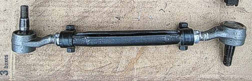
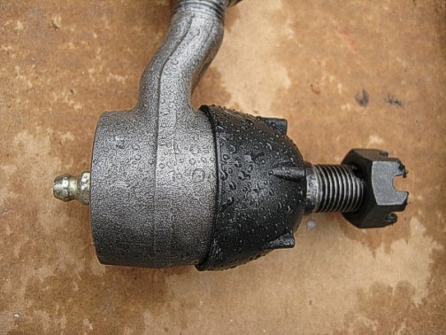
Install the grease boots on the tie rod studs and screw in the new grease zerks. To install the tie rod assembly, connect the tie rod ends to the steering knuckle arm and the center link. Install the nuts and tighten them to 40 foot-pounds and install the cotter pins. Lube each tie rod end and the idler arm with the Mopar grease in your grease gun. Below left: The new tie rod assembly is shown without the new grease boot. Right: the new boot and grease zerk is installed on the tie rod end.
Now is the best time to inspect and repack the front wheel bearings--both inner and outer--and replace the grease seal. Install the rotor on the spindle next. Install the outer bearing and thrust washer and the nut in that order. Tighten the wheel bearing adjustment nut to 90 inch-pounds, while rotating the rotor. Align the lock nut on the nut with one pair of slots in line with the cotter pin hole in the spindle. Back off the adjusting nut and lock assembly one slot. Install the cotter key. Install the grease cap.
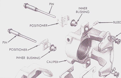
Inspect the front brake pads and replace if necessary. Position the brake caliper over the rotor and align the holes for the pins. Place the positioner clips (commonly referred to as anti-rattle clips) over the pins --see reference diagram below. Apply silicone lubricant to the pins and any surface that the caliper slides on--DON'T get any on the rotor or brake pads!! Install the pins with the positioners open end towards the outside and the arrows pointing upward. Be very careful when starting these pins, as it is very easy to cross-thread them. Tighten the pins to 35 foot-pounds.
Note: Two of our positioner clips broke during disassembly. These are no longer available from Chrysler and the only vendor we could find that had them available is Mega Parts. They refer to the clips as "disc brake anti-rattle clips" and a set of four cost $35 plus shipping. You can order them on the phone at (608) 452-2045 or by them online at: www.megapartsusa.com

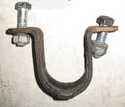
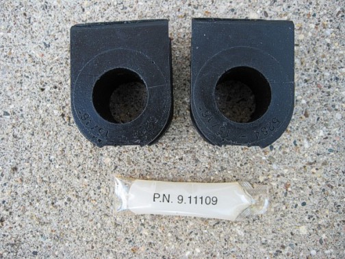
Install your front sway bar by holding it with both ends pointing toward the front of the car. Slide the bar through the hole in the front cross-member (doesn't matter which side you put it in through) and flip it over so the connecting holes are back near the lower control arms. Locate your old sway bar bracket (shown below left) and lube the inner hole in the new bushings with the lube supplied in your PST kit (shown below right).
Install one new bushing on each side of the sway bar out near the bend in the bar. The bushings are split so you can wrap them around the bar. Place the bracket over the bushing and align it with the hole in the cross-member. Put the bolts in it and tighten to 200 inch-pounds. Repeat this installation for the other bracket/bushing. The photo below left shows the new sway bar link parts that come in the PST kit. Our PST kit had two types of link assemblies in it. One of them is pictured below. The bolt is longer than our original part. The other assembly only included the washers and bushings to use with our old bolt. We opted to use the all-new longer assembly. It doesn't matter which you use. The photo at right shows the correct order of assembly after installation of the new bushings/washers.
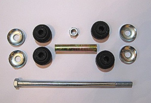
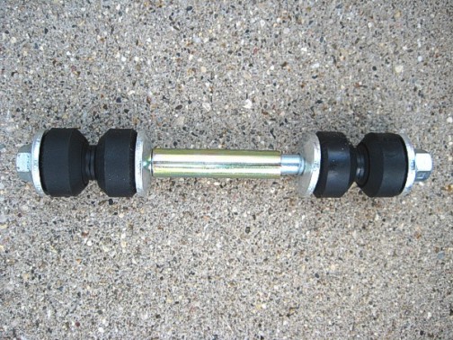
To begin assembly of the link, place one of the retainer washers--cup side up--and slide it to the end of the bolt. Place a bushing with the rounded side toward the retainer washer and slide it on. Start this assembly through the sway bar. Install a bushing with the cone end slid down against the sway bar. Put another retainer washer on with the cupped side down against the bushing. Slide on the metal sleeve. Next slide on another retainer washer with the cupped side up, then a bushing with the rounded side against the washer. Put a bushing with the cone side down against the last bushing and a retainer washer with the cupped side down. Start the nut on finger-tight. Repeat this same assembly at the other end of the sway bar.
It really helps if you have assistance with this next procedure. Raise the sway bar, align it with the hole in the lower control arm. Take the nut off the top retainer washer and remove the top bushing. While holding the assembly up and aligned with the hole, place the link assembly bolt through the hole in the lower control arm. Install the upper bushing cone side down, then the retainer washer cupped side down. Install the nut and torque it to 100 inch-pounds.
Repeat all of the above instructions on the other side of the vehicle. Install the tires and wheels and tighten the lug nuts to 65 foot-pounds. Let the car down off the blocks. Bounce the body a few times and measure the ride height at the same point on the body that you used before you began the disassembly. An adjustments higher or lower that are needed can now be made using the torsion bar adjuster bolts in the lower control arm. This will get your height close and then the front-end alignment shop will tweak it when they do the alignment. Anything that affects the height of the rear of the car (air shock pressure, etc) needs to be adjusted before going to the shop for alignment. Also, to keep the front-end alignment true, those components need to be maintained at their height.
Last, but most importantly, after the front-end alignment, drive and enjoy! Your car will feel better than it did in 1970 when it was brand new. Note: this tech article is for 1970 B-body only. 1969 B-bodies are a different procedure and use a different rebuild kit.
| MAIN PAGE | TABLE OF CONTENTS |